26+ rules of use case diagrams
A use case diagram consists of use cases actors and relationships between them. The first kind is when the rule is embedded directly in the use case.

Jd Edwards 9edge
A use case diagram is a visual representation of the different ways and possible scenarios of using a system.

. Use Case A use case or just UC is a set of actions that lead to a particular goal. Use-case should reflect user needs and goals and should be initiated by an actor. Only then can they be refined and.
A use case can be. Use Case Diagram Notations Use cases define interactions between external actors and the system to attain particular goals. Always structure and organize the use case diagram from the perspective of actors.
In this particular situation I would. Show what you think are interesting relationships in the model. There are no strict rules about what to illustrate in use-case diagrams.
Use case diagram can be imagined as a black box where only the input output and the function of the black box is known. The definition and relevance of the. It encapsulates the systems functionality by incorporating use cases actors and their relationships.
Use Case Diagrams There are various products developed for visualizing Use Case models such as Visual UML GD Pro Smart draw Rational Rose Microsoft Visio etc. They are no longer lost but are. Approach 1 is an improvement because it contains a place for business rule statements usually at the bottom of a use case template.
Business actors Customers participating in the business use-case should be connected to the use-case. A use case diagram is used to represent the dynamic behavior of a system. I agree with Konamiman that some flexibility in what we should do with our diagrams is reasonable our objective is to communicate.
Reference other use cases when appropriate Lets. A use case diagram contains four main components Actor. Validate card information before.
Use cases should start off simple and at the highest view possible. To document the business rules associated with a UML statechart there are five elements that must be documented. The following diagrams may be of interest.
It illustrates how a user will perform actions and interact with a. In a use case we aim to capture the interaction of the user with the system and not necessarily detailed system logic. The very order of steps in the use case might constitute a business rule eg.
These diagrams are used at a very high level of design.
1

Energy Level Structure Of The 4d 4f Ground Configuration Level Download Scientific Diagram
Landlord Quit Notice Letter

The Transitions Diagram Of M1 And E2 Electric Dipole Forbidden Download Scientific Diagram
Landlord Quit Notice

Ennv Ex993 151 Htm
Solved A Group Of 191 Students Of Which 10 Are Taking French Business And Music 36 Are Taking French And Business 20 Are Taking French And Mus Course Hero

A Charge State Series For The Native Adh Tetramer After Online Sec Download Scientific Diagram

Diy Biophilia Development Of The Biophilic Interior Design Matrix As A Design Tool Mcgee 2019 Journal Of Interior Design Wiley Online Library

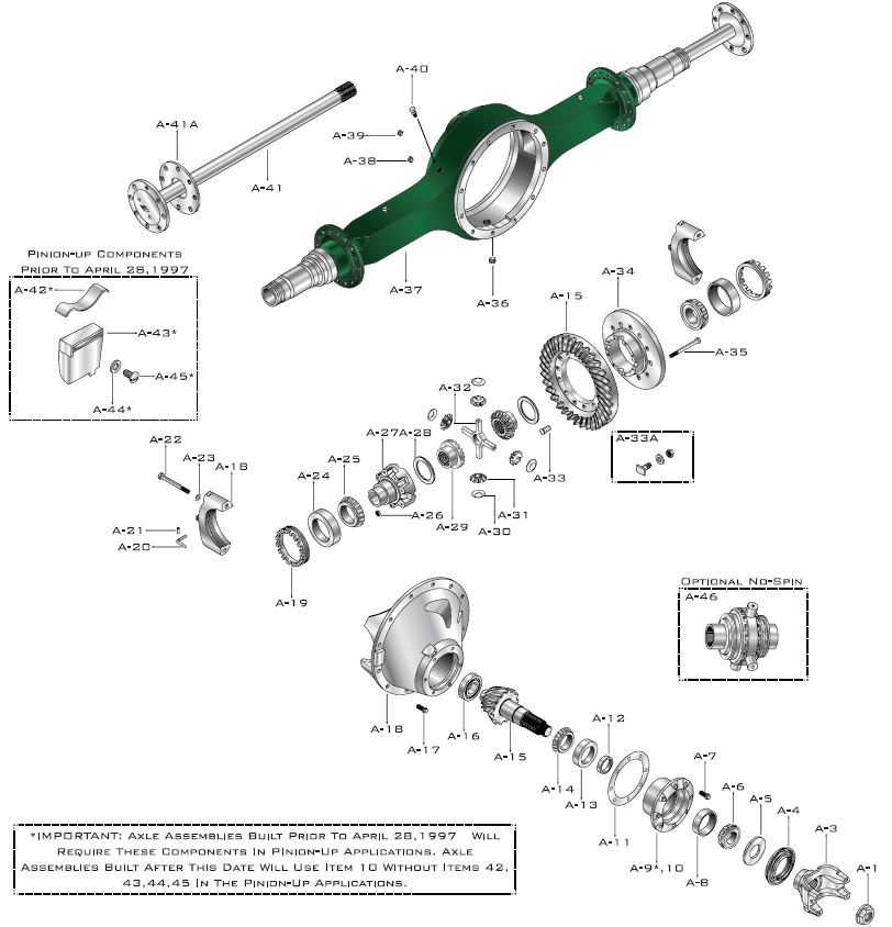
Axle Components W230 S 1a Gearcentre Canada Heavy Light Duty Transmissions Differentials Pto Transfer Case

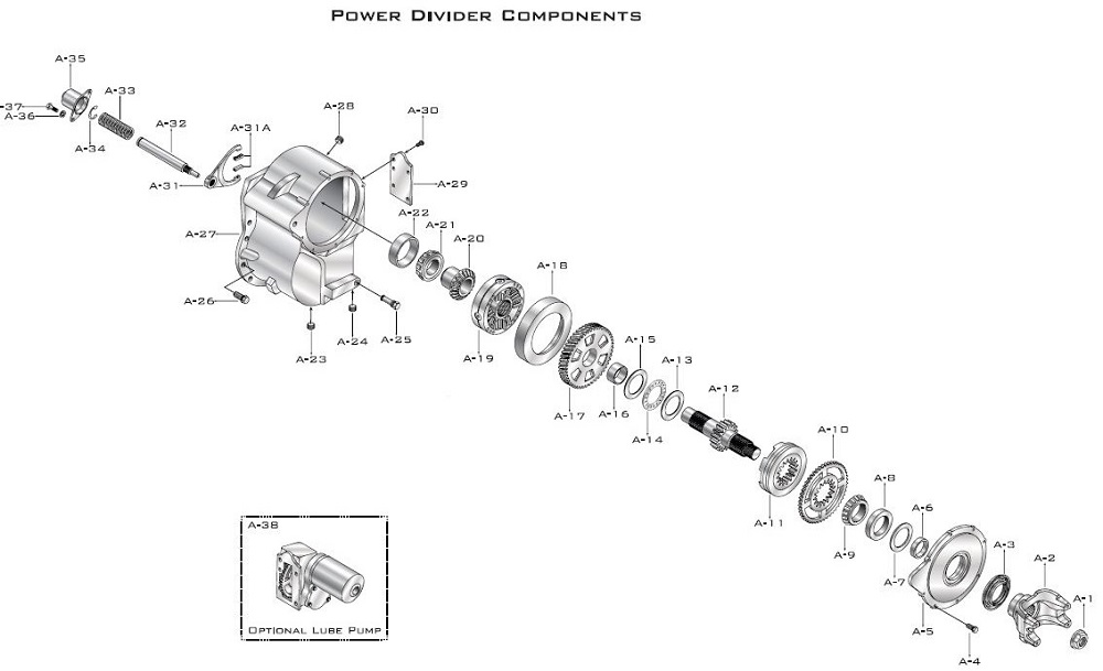
Power Divider Components N400 S 2a Gearcentre Canada Heavy Light Duty Transmissions Differentials Pto Transfer Case

The Kr 26 2 3 Spectrum With Satellites Composite Over Several Similar Download Scientific Diagram

The Kr 26 2 3 Spectrum With Satellites Composite Over Several Similar Download Scientific Diagram

A Native Top Down Ecd Spectrum Of 26 Adh Tetramer Using The Download Scientific Diagram

Requirements Traceability Matrix Business Analyst Business Analysis Business Template

Use This Random Picker Wheel To Decide A Choice Clean Randomizer Wheel Design Enter Choice Pick A Random Number Random Choice Generator Online Learning Games
1